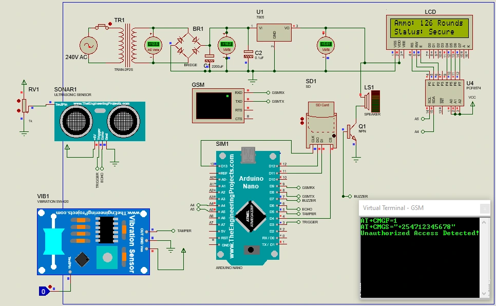
Designing and simulating a power supply circuit is a fundamental skill for electronics enthusiasts and professionals. In this blog, we’ll walk through the process of simulating a 5V power supply in Proteus. We’ll use an alternator, a step-down transformer, a bridge rectifier, a filter capacitor, a voltage regulator (LM7805), and a smoothing capacitor. By the end of this guide, you’ll have a clear understanding of how to set up and simulate this circuit.
Components Required for 5V Power Supply
- Alternator
- Voltage: 325V
- Frequency: 50Hz
- Step-down Transformer
- Primary Inductance: 4H
- Secondary Inductance: 0.0119H
- Coupling Factor: 1
- Primary DC Resistance: 200mΩ
- Secondary DC Resistance: 0.6557mΩ
- Bridge Rectifier
- Diodes: 1N4007 (4 pieces)
- Filter Capacitor
- Capacitance: 2200uF
- Voltage Regulator
- LM7805
- Smoothing Capacitor
- Capacitance: 100uF
Step-by-Step Guide to Simulation
Step 1: Set Up the Alternator
First, we need to set up the alternator in Proteus.
- Place the Alternator:
- Open Proteus and place an alternator from the components library.
- Set the alternator voltage to 325V and frequency to 50Hz.
Step 2: Configure the Step-down Transformer
Next, we’ll set up the transformer to step down the high voltage from the alternator to a lower voltage suitable for the rectifier and regulator stages.
- Place the Transformer:
- Place a transformer from the components library.
- Set the primary inductance to 4H and the secondary inductance to 0.0119H.
- Set the coupling factor to 1.
- Set the primary DC resistance to 200mΩ and secondary DC resistance to 0.6557mΩ.
Step 3: Design the Bridge Rectifier
The bridge rectifier converts the AC voltage from the transformer to a pulsating DC voltage.
- Place the Diodes:
- Place four 1N4007 diodes in a bridge configuration.
- Connect the Bridge Rectifier:
- Connect the secondary winding of the transformer to the rectifier.
Step 4: Add the Filter Capacitor
To smooth the pulsating DC output from the bridge rectifier, we add a filter capacitor.
- Place the 2200uF Capacitor:
- Connect the 2200uF capacitor across the output of the bridge rectifier.
Step 5: Insert the Voltage Regulator
The LM7805 voltage regulator will provide a stable 5V DC output.
- Place the LM7805:
- Connect the output of the filter capacitor to the input pin of the LM7805 voltage regulator.
- Ground the ground pin of the LM7805.
- The output pin of the LM7805 will provide a regulated 5V DC output.
Step 6: Connect the Smoothing Capacitor
To further smooth the output voltage, we add a 100uF capacitor.
- Place the 100uF Capacitor:
- Connect the 100uF capacitor across the output of the LM7805.
Running the Simulation
- Run the Simulation:
- After completing the circuit, run the simulation in Proteus.
- Observe the output voltage across the smoothing capacitor.
- The output is a stable 5V DC.
Troubleshooting Tips
- Check Connections: Ensure all components are correctly connected according to the circuit diagram.
- Component Values: Verify that all component values are set as specified.
- Simulation Settings: Ensure the simulation settings in Proteus are correctly configured for accurate results.
Applications and Future Enhancements
This 5V power supply can be used in various applications such as powering microcontrollers, sensors, and other low-voltage electronic circuits. Future enhancements could include adding a display to monitor the output voltage, incorporating a current limiting feature, or designing a printed circuit board (PCB) for the power supply.
Conclusion
Simulating a 5V power supply in Proteus is a valuable exercise that helps you understand the intricacies of power supply design. By following this guide, you can create a reliable 5V power supply circuit and gain practical experience in electronic simulation. Whether you’re a beginner or an experienced electronics enthusiast, this project is a great way to enhance your skills and knowledge. For more detailed projects and tutorials, visit our website.


Leave a Reply