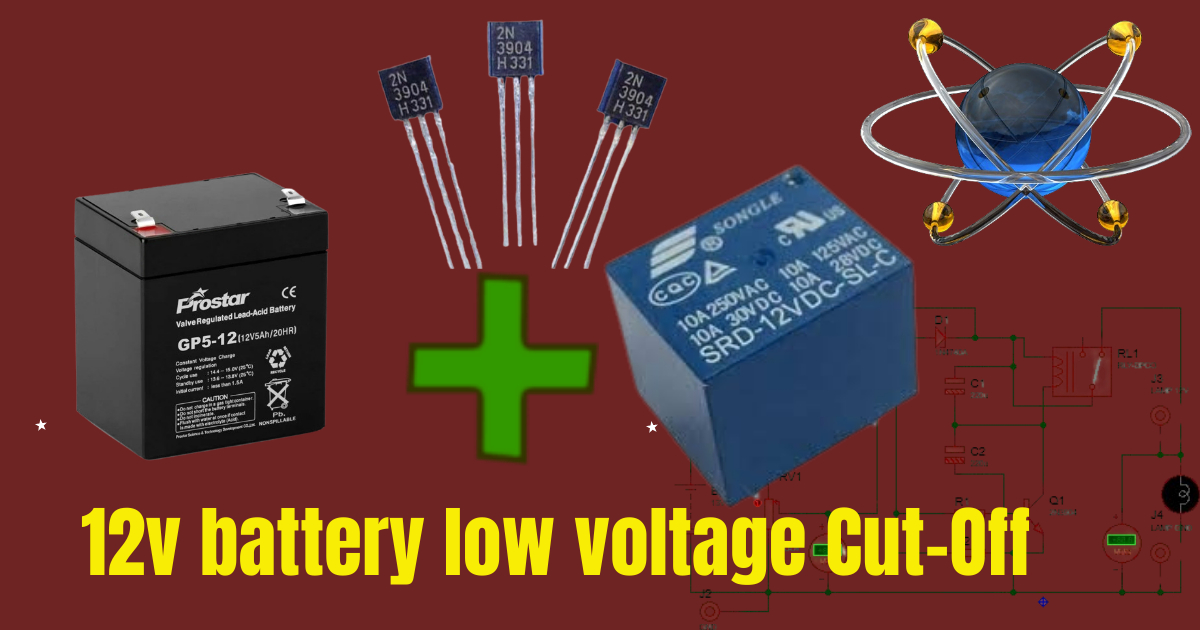
Maintaining the health and longevity of your 12V battery is crucial, especially when it powers essential equipment. One effective way to protect your battery from deep discharge is by implementing a low voltage cut-off circuit. In this blog post, we will guide you through the process of building a 12V battery low voltage cut-off using simple and readily available components.
Components Needed
- 12V battery
- 500K trimmer (potentiometer)
- 1N4740A Zener diode
- Two 220uF capacitors
- Two 1K resistors
- 2N3904 NPN transistor
- 12V relay
- Output lamp as load
Circuit Design of Low Voltage Cut-Off system
The low voltage cut-off circuit is designed to disconnect the load from the battery when the battery voltage drops below a preset threshold. This helps prevent the battery from being discharged to a level that could cause damage or reduce its lifespan.
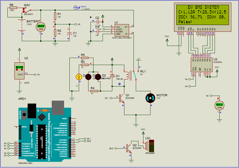
Circuit Diagram
Here is a basic layout of the circuit components:
- Voltage Sensing and Reference:
- The 1N4740A Zener diode is used to create a stable reference voltage.
- The 500K trimmer is used to set the cut-off voltage threshold.
- Transistor Switching:
- The 2N3904 NPN transistor acts as a switch, controlling the relay based on the battery voltage.
- Relay Control:
- The relay is used to connect or disconnect the load (output lamp) based on the transistor’s state.
Step-by-Step Assembly
Step 1: Setting Up the Voltage Reference
- Zener Diode Configuration:
- Connect the anode of the 1N4740A Zener diode to the ground.
- Connect the cathode of the Zener diode to one end of a 1K resistor.
- Connect the other end of the 1K resistor to the positive terminal of the 12V battery.
- This creates a stable reference voltage of approximately 10V (the breakdown voltage of the 1N4740A).
- Voltage Divider and Trimmer:
- Connect the middle pin of the 500K trimmer to the junction between the Zener diode and the 1K resistor.
- Connect one end of the trimmer to the positive terminal of the 12V battery.
- Connect the other end of the trimmer to the ground.
Step 2: Transistor Switching
- Transistor Configuration:
- Connect the base of the 2N3904 transistor to the wiper (adjustable pin) of the 500K trimmer through another 1K resistor.
- Connect the emitter of the 2N3904 transistor to the ground.
- Connect the collector of the 2N3904 transistor to one end of the relay coil.
Step 3: Relay Control
- Relay Connection:
- Connect the other end of the relay coil to the positive terminal of the 12V battery.
- Connect the common terminal (COM) of the relay to the positive terminal of the battery.
- Connect the normally open (NO) terminal of the relay to one end of the output lamp.
- Capacitors for Stability:
- Place a 220uF capacitor across the 12V battery terminals to filter any voltage spikes.
- Place another 220uF capacitor across the relay coil to ensure stable operation.
Detailed Explanation
Voltage Reference and Divider
The Zener diode provides a stable 10V reference voltage. The 500K trimmer forms a voltage divider with this reference, allowing you to set a precise cut-off voltage. When the battery voltage drops below the set threshold, the voltage at the base of the 2N3904 transistor drops, turning it off.
Transistor Switching
The 2N3904 transistor is used as a switch. When the battery voltage is above the threshold, the transistor remains on, allowing current to flow through the relay coil, keeping the relay activated. When the battery voltage drops below the threshold, the transistor turns off, deactivating the relay.
Relay Control
The relay controls the connection between the battery and the load (output lamp). When the relay is activated, the load is connected to the battery. When the relay is deactivated (due to low battery voltage), the load is disconnected, preventing further discharge of the battery.
Testing and Calibration
- Initial Setup:
- Assemble the circuit on a breadboard or PCB, ensuring all connections are secure.
- Power On:
- Connect the 12V battery and power on the circuit.
- Calibrate Cut-Off Voltage:
- Adjust the 500K trimmer until the relay deactivates at the desired cut-off voltage. Use a multimeter to monitor the battery voltage during this process.
- Verify Operation:
- Connect the output lamp and observe the circuit’s behavior. The lamp should turn off when the battery voltage drops below the set threshold.
Conclusion
Building a 12V battery low voltage cut-off circuit using a 500K trimmer, Zener diode, and a few other components is a practical and valuable project for anyone looking to protect their batteries from deep discharge. This simple yet effective circuit ensures the longevity of your battery by automatically disconnecting the load when the voltage drops too low. Follow the steps outlined in this blog post to create your own low voltage cut-off circuit and enjoy the benefits of extended battery life and reliability.


Leave a Reply