
In the evolving world of electric vehicles (EVs), battery performance is one of the most critical aspects for ensuring safety, efficiency, and long-term reliability. To achieve this, an efficient Battery Management System (BMS) is essential. In this post, we’ll walk through how to build a simple yet comprehensive EV BMS using Arduino. We will focus on real-time monitoring of key battery parameters like voltage, current, temperature, and the calculations for State of Charge (SOC) and State of Health (SOH), which are crucial for maintaining battery health.
Why an EV Battery Management System (BMS) Matters
The Battery Management System is responsible for monitoring and managing the battery pack’s performance to avoid damage, overcharging, or overdischarging, which can reduce the battery’s lifespan. A typical BMS measures key parameters such as:
- Voltage: Ensures the battery voltage is within safe operating limits.
- Current: Measures the flow of electricity in and out of the battery.
- Temperature: Monitors the temperature to prevent overheating.
- State of Charge (SOC): Shows the remaining charge in the battery, expressed as a percentage.
- State of Health (SOH): Estimates the overall health of the battery over time, factoring in its capacity and age.
By properly monitoring these parameters, a BMS can prevent accidents such as overheating or battery degradation, ensuring the EV remains safe and functional.
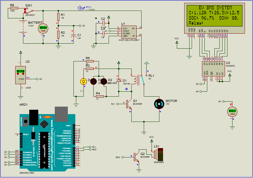
Components Used in Building the BMS
To monitor the health of the battery pack, the following components are essential:
- Arduino Board (e.g., Arduino Uno or Nano)
- Voltage Sensor (e.g., voltage divider or direct input for battery voltage)
- Current Sensor (e.g., ACS712 Hall-effect sensor for current measurement)
- Temperature Sensor (e.g., LM35 or TMP36 for measuring temperature)
- 20×4 LCD Display (with I2C interface for displaying data)
- Relay (to disconnect the battery under certain conditions)
- Buzzer (for warning about critical conditions, like low SOC)
Detailed Breakdown of Each Sensor and Its Role
1. Voltage Sensor
The Voltage Sensor is used to measure the battery’s voltage. It’s one of the most critical parameters because the voltage of the battery indicates its charge level. For a 12V Li-ion battery, voltage should remain between a safe range of 9.6V (discharge cutoff) to 12.6V (fully charged). If the voltage falls below this range, it can damage the battery or cause unsafe conditions.

To measure the voltage:
- Use an analog-to-digital converter (ADC) on the Arduino to read the voltage level from the battery through a voltage divider or direct analog input.
- Scaling is crucial because the Arduino’s ADC reads values from 0 to 1023, so we need to scale the reading back to the actual battery voltage.
The formula to calculate the battery voltage is:
Battery Voltage=(Analog Reading×5.0/1023.0)×(Vmax/5.0)
Where:
Analog Readingis the value read by the ADC.Vmaxis the maximum voltage of the battery (12.6V for a fully charged 12V battery).
2. Current Sensor (ACS712)
The ACS712 current sensor measures the amount of current flowing through the battery. The current sensor provides an analog output that varies with the current being drawn or supplied by the battery. The current value can be extracted by calculating the difference between the output voltage and the reference voltage.

The ACS712 has the following characteristics:
- It outputs a voltage of 2.5V when no current is flowing (this is the reference voltage, Vref).
- It has a sensitivity of 185mV per ampere (0.185V/A), meaning that for every ampere of current, the output voltage will change by 185mV.
The formula to calculate the current is: Battery Current (A)=Voltage at Sensor−Vref / Sensitivity (mV/A)
Where:
Voltage at Sensoris the ADC reading scaled to voltage.Vrefis the reference voltage of the ACS712 (typically 2.5V).Sensitivityis 0.185V/A.
3. Temperature Sensor (LM35)
The LM35 is a simple temperature sensor that provides an analog voltage output proportional to the temperature in degrees Celsius. The temperature of the battery is crucial because if it overheats, it can cause damage or safety risks. By reading the temperature value, we can ensure the battery stays within safe operating temperatures, typically around 20°C to 40°C for most lithium-ion batteries.
The formula to calculate the temperature is:
Temperature (°C)=(Analog Reading×5.0 / 1023.0)×100.0
This converts the analog input to a temperature value. The LM35 provides a 10mV/°C output, so the temperature calculation is scaled accordingly.
4. State of Charge (SOC)
SOC is a measure of how much charge is remaining in the battery and is expressed as a percentage. It can be calculated using the following formula:
SOC=((Battery Voltage−Vmin) / (Vmax−Vmin))×100
Where:
Vminis the minimum safe voltage (9.6V for the 12V battery).Vmaxis the maximum voltage (12.6V for the 12V battery).Battery Voltageis the current voltage reading from the sensor.
SOC helps determine when to charge or stop discharging the battery to avoid deep discharges that can degrade battery health.
5. State of Health (SOH)
SOH measures the overall condition of the battery, including its ability to hold charge compared to its original capacity. This is typically calculated as a percentage based on the battery’s current capacity versus its nominal capacity.
For example, if a 10Ah battery has only 8Ah of usable capacity, its SOH is:
SOH=(8 / 10)×100=80%
SOH helps monitor battery aging and is a useful indicator for when the battery may need to be replaced.
The Code – Battery Management System
#include <Wire.h> #
include <LiquidCrystal_I2C.h>
#define VOLTAGE_SENSOR A0
#define CURRENT_SENSOR A1
#define TEMP_SENSOR A2
#define RELAY_PIN 7
#define BUZZER 8
LiquidCrystal_I2C lcd(0x27, 20, 4);
// Battery parameters
float batteryVoltage, batteryCurrent, temperature, SOC, SOH;
float Vmax = 12.6; // Max voltage of a 12V Li-ion pack
float Vmin = 9.6; // Min voltage before cut-off
float nominalCapacity = 10.0; // Battery rated capacity in Ah
// ACS712 Current Sensor calibration
float Vref = 2.5; // Reference voltage at 0A (for ACS712)
float sensitivity = 0.185; // Sensitivity of ACS712 (185mV/A)
void setup() {
Serial.begin(9600);
lcd.init();
lcd.backlight();
pinMode(RELAY_PIN, OUTPUT);
pinMode(BUZZER, OUTPUT);
}
void loop() {
// Read Voltage (scaled to battery voltage)
batteryVoltage = analogRead(VOLTAGE_SENSOR) * (5.0 / 1023.0) * (12.6 / 5.0);
// Read Current (ACS712, assuming 2.5V reference at 0A)
int currentRaw = analogRead(CURRENT_SENSOR);
float voltageAtSensor = currentRaw * (5.0 / 1023.0); // Read voltage from sensor
batteryCurrent = (voltageAtSensor - Vref) / sensitivity; // Calculate current in Amps

// Read Temperature (arbitrary scaling factor, can be adjusted)
temperature = (analogRead(TEMP_SENSOR) * (5.0 / 1023.0)) * 100.0;

// Calculate SOC (State of Charge)
SOC = ((batteryVoltage - Vmin) / (Vmax - Vmin)) * 100.0;
SOC = constrain(SOC, 0, 100); // Keep SOC between 0% and 100%

// Simulated SOH Calculation (assuming 8Ah remaining from 10Ah)
SOH = (8.0 / nominalCapacity) * 100.0;

// Clear the LCD before updating values
lcd.clear();

// First Line: EV BMS SYSTEM
lcd.setCursor(4, 0);
lcd.print("EV BMS SYSTEM");

// Second Line: Current, Temp, Voltage
lcd.setCursor(0, 1);
lcd.print("C:");
lcd.setCursor(2, 1);
lcd.print(batteryCurrent, 2);
lcd.print("A");

lcd.setCursor(8, 1);
lcd.print("T:");
lcd.setCursor(10, 1);
lcd.print(temperature, 1);
lcd.print("C");

lcd.setCursor(14, 1);
lcd.print("V:");
lcd.setCursor(16, 1);
lcd.print(batteryVoltage, 2);
lcd.print("V");

// Third Line: SOC, SOH
lcd.setCursor(0, 2);
lcd.print("SOC:");
lcd.setCursor(5, 2);
lcd.print(SOC, 1);
lcd.print("%");

lcd.setCursor(12, 2);
lcd.print("SOH:");
lcd.setCursor(17, 2);
lcd.print(SOH, 1);
lcd.print("%");

// Fourth Line: Relay & Buzzer State
lcd.setCursor(0, 3);
lcd.print("Relay:");
lcd.setCursor(7, 3);
lcd.print(digitalRead(RELAY_PIN) ? "ON " : "OFF");

lcd.setCursor(12, 3);
lcd.print("Buzzer:");
lcd.setCursor(19, 3);
lcd.print(digitalRead(BUZZER) ? "ON " : "OFF");

// Safety Conditions
if (SOC < 20) {
    digitalWrite(RELAY_PIN, LOW);  // Cut-off discharge
    digitalWrite(BUZZER, HIGH);    // Alert low battery
} else {
    digitalWrite(RELAY_PIN, HIGH);
    digitalWrite(BUZZER, LOW);
}

delay(1000);
}


Leave a Reply