
Pulse Induction Device Using LM358
A pulse induction device using LM358 is a powerful tool in detecting minute biological signals, making it useful for medical and scientific applications. This project will provide you with a comprehensive understanding of how pulse induction works and how to implement it using basic electronic components.
Components Needed
To build your pulse induction device using LM358, gather the following components:
- LM358 Operational Amplifier: This dual op-amp is central to amplifying the signals detected by the device.
- 27V Power Supply: Provides the necessary voltage to power the circuit.
- 100uF Capacitor: Used for stabilizing the power supply and filtering.
- 100k and 150k Resistors: These resistors help set the gain and biasing of the op-amp.
- 1M Resistors: Used for further stabilization and signal conditioning.
- Copper and Brass Leads: These leads will attach to the skin veins to detect the pulses.
- Switch: Used to power the device on and off.
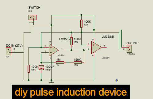
Circuit Diagram and Assembly of Pulse Induction Device
Before assembly, let’s outline the circuit diagram for the pulse induction device using LM358. The key idea is to use the LM358 to amplify the tiny electrical signals generated by the pulses in the veins.
- Power Supply and Decoupling: Connect the 27V power supply to the LM358. Place the 100uF capacitor across the power supply to smooth out any fluctuations.
- Input Stage: Connect the copper and brass leads to the inverting and non-inverting inputs of the LM358 through 100k resistors. This setup will help in picking up the pulse signals from the skin veins.
- Feedback Network: Create a feedback loop using the 150k resistors. This loop determines the gain of the amplifier. Connect one 150k resistor between the output and the inverting input of the LM358, and another 150k resistor from the inverting input to ground.
- Signal Conditioning: Add the 1M resistors in parallel with the 150k resistors to stabilize the signal further and reduce noise.
- Output Stage: The output from the LM358 can be connected to a display or a recording device to monitor the pulse signals. You can use an oscilloscope or a simple LED indicator to visualize the pulses.
- Switch: Integrate a switch into the power supply line to easily turn the device on and off.
Testing and Troubleshooting
After assembling the circuit, it’s time to test your pulse induction device. Follow these steps:
- Initial Power-On: Turn on the device using the switch and observe if the circuit powers up correctly.
- Signal Detection: Attach the copper and brass leads to your skin veins, ensuring good contact.
- Output Observation: Monitor the output on an oscilloscope or through the LED indicator. You should see a pulsing signal corresponding to your heartbeat.
If the device doesn’t function as expected, check the following:
- Connections: Ensure all connections are secure and correctly placed as per the circuit diagram.
- Component Values: Verify the values of the resistors and capacitors to ensure they are correct.
- Power Supply: Confirm that the power supply is providing the correct voltage without significant fluctuations.
Applications and Future Enhancements
A pulse induction device using LM358 can be applied in various fields:
- Medical Monitoring: Used for non-invasive pulse detection in medical diagnostics.
- Biometric Measurements: Utilized in wearable technology for health and fitness monitoring.
- Scientific Research: Helps in studying physiological signals and their patterns.
Future enhancements could include:
- Digital Display: Adding a digital display to show the pulse rate directly.
- Wireless Transmission: Integrating a wireless module to transmit data to a smartphone or computer.
- Noise Reduction: Incorporating additional filtering stages to reduce ambient noise and improve signal clarity.
For more detailed projects and tutorials, visit our website where we explore a wide range of electronic projects and innovations.
To deepen your understanding of the components used in this project, check out these resources:
Conclusion
Building a pulse induction device using LM358 is a rewarding project that bridges the gap between simple electronics and practical medical applications. By following this guide, you will not only gain hands-on experience with operational amplifiers and signal processing but also create a useful tool for detecting and monitoring biological signals. So, gather your components, follow the steps, and embark on this exciting journey of building a pulse induction device.

Leave a Reply